DecaBox MIDI to DMX Converter
Simple, straightforward bridging between MIDI and lighting control.
- Basic System Information
- Quick Start
- Step 1: Set the DecaBox to the Correct MIDI Channel
- Step 2: Set the DMX Equipment to a Known Start Address
- Step 3: Use MIDI Monitor Mode to Confirm Valid Data
- Step 4: Exit ‘MIDI Monitor’ and Drive the Lighting Equipment
- Example: An RGB Stage Light
- The Internal Dimming Engine
- Drive the DMX Engine Using MIDI Continuous Controller (CC) Messages
- References
- DMX-512 for Musicians: a Quick Analogy
- Purchasing
- Case Study - A Series of Generic LED PARs from Asia
Basic System Information
This firmware personality for the DecaBox receives MIDI note and CC information on a user-specified MIDI channel. This data is converted to DMX512 lighting data. In the standard firmware version, the first 128 DMX channels can be controlled in real time via MIDI.
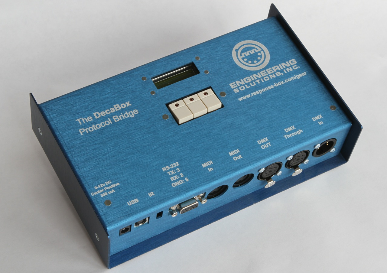
- The system ships with an international switching power supply. System power requirements are 9-12v DC, center positive, 300 mA. The power supply connector has standard dimensions of 2.1mm x 5.5mm.
- MIDI data is received via the 5 pin ‘MIDI In’ jack. MIDI data is passed through (a mirror of the input) via MIDI out.
- DMX lighting data is generated on the Neutrik 5 pin XLR female jack. If necessary, a 5 pin to 3 pin adapter cable may used to connect various lighting fixtures.
The DecaBox USB port is used for firmware updates. It does not accept MIDI data.
Other firmware builds are available which allow access to an entire universe of DMX data via MIDI. Contact Engineering Solutions for caveats and more information.
Originally, the lighting guys wanted to keep their wiring separate from the audio crew, who were using XLR-3 microphone cable; thus the 5 pin lighting data standard. However, in nearly every current implementation of DMX control only pins 1, 2 and 3 are used. The 5 pin connectors cost about $2 more in quantity, so some manufacturers eschew them for less expensive 3 pin versions. Professional and touring gear still relies nearly exclusively on the 5 pin infrastructure. In either case, pin 1 is ground, pin 2 is ‘data complement’ or D- and pin 3 is ‘data true’ or D+. For even more gory detail, see the appendix.
Quick Start
How to Easily and Accurately Control DMX Lighting Gear From Your Existing MIDI Equipment
Kick that grumpy lighting guy to the curb while retaining complete creative control.
It’s a question we hear nearly every week. “We’re in a band. We use a sequencer for backing tracks and to send ‘click’ to the drummer. We’d like to control our lighting equipment from the sequencer as well. That way, the light show for each song will be exactly synchronized with our music, and no important cues will be missed. Can you help?”
Or perhaps, “We’re designing an art installation. Every time someone jumps on these larger-than-life piano keys we’ve built, we need a different stage light to flash in sync. Can you help?
Fortunately, the answer is a very definite ‘yes’ to all of these questions.
The DecaBox Protocol Bridge with MIDI to DMX firmware easily, quickly and accurately converts MIDI note and CC messages into DMX channel values. This makes it very, very easy to program a light show from within MIDI software and hardware, or even drive lights in real time from a keyboard or drum kit.
It’s been used all over the world, for many years now, by artists, musicians, lighting designers and other creative people. The next few pages describe how the system works, and show how to quickly begin using this hardware as part of your next production.
Follow these instructions to get up and running quickly. Each step is described in detail in the following pages:
- Set the DecaBox to the correct MIDI channel.
- Set the DMX equipment to a known start address. Note that the right LED on the DecaBox is illuminated, signifying that DMX data is being generated. Check your receiving equipment - it may also contain an LED indicator to confirm data being present.
- Use the ‘MIDI Monitor’ function on the DecaBox to confirm valid data is being received. The left LED on the DecaBox will flicker as MIDI data is received.
- Exit ‘MIDI Monitor’ and drive the lighting equipment directly, using any combination of Note On / Note Off / Midi Patch Change / MIDI Continuous Controller messages.
-
Note: connected DMX equipment will not respond in monitor mode. The DecaBox is only displaying incoming data. To resume MIDI to DMX conversion, use the left pushbutton to 'ESC' from monitoring mode.
Step 1: Set the DecaBox to the Correct MIDI Channel
In the MIDI world, there are 16 channels available. Between 1 and 16 channels can be transmitted via a single MIDI cable. During initial setup, it’s best to restrict the MIDI output of your equipment (be it a guitar pedal, a sequencer, a keyboard, or similar) to a single MIDI channel. This way, the wire is ‘quiet’ with the exception of MIDI data being used to control lighting equipment.
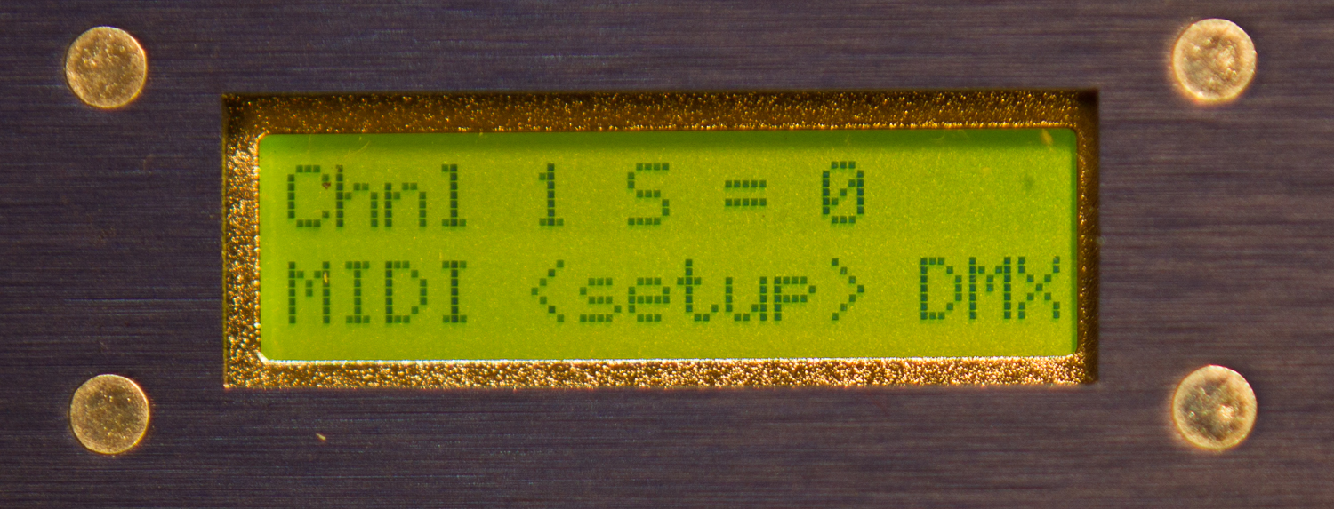
Press the center pushbutton which corresponds to ‘setup’ on the LCD screen.
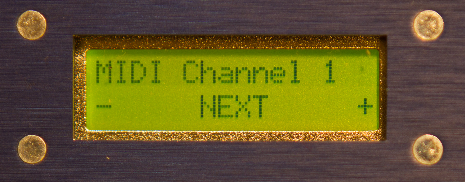
Then, use the left and right buttons to set the desired MIDI channel. When finished, press the center button ‘Next.’
If no other settings are required, choose ‘Next’ several more times, skip through the MIDI monitor mode, and let the system resume its home / startup screen, #1 above.
Step 2: Set the DMX Equipment to a Known Start Address
When we do telephone support, we often suggest setting the first lighting fixture to DMX channel 60. This makes it easy to access via the musical notes near the middle C octave. Once the system is stable, the DMX start address can be set to any number in the range [1 128].
Your DMX equipment will have a manual for making this change. It may involve setting DIP switches or manipulating buttons on a front panel.
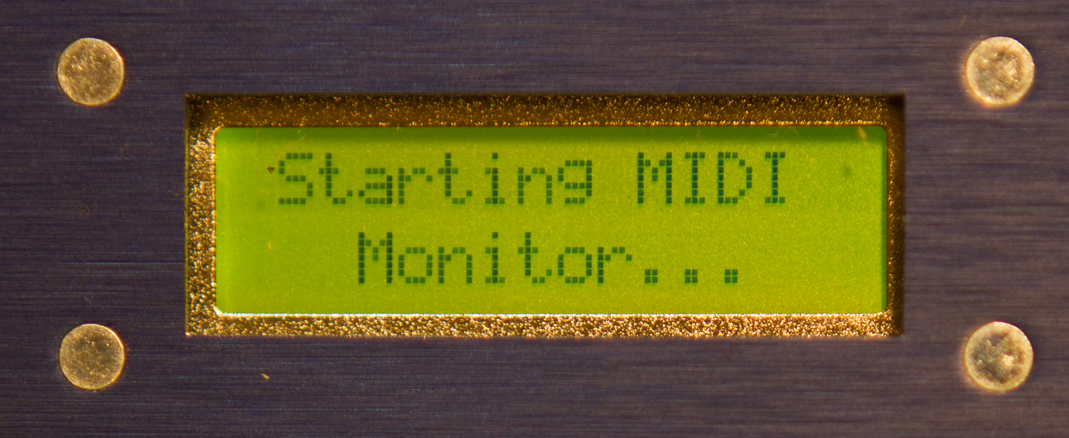
Step 3: Use MIDI Monitor Mode to Confirm Valid Data
The MIDI monitor screen is several functions deep from the main run screen. It can be accessed by pressing the center ‘setup’ button, then ‘next’ several times. The first screen will display this text:
On this screen, a sample MIDI note on message was transmitted. The DecaBox interprets it as being on MIDI channel 1, Note #55, Velocity 100: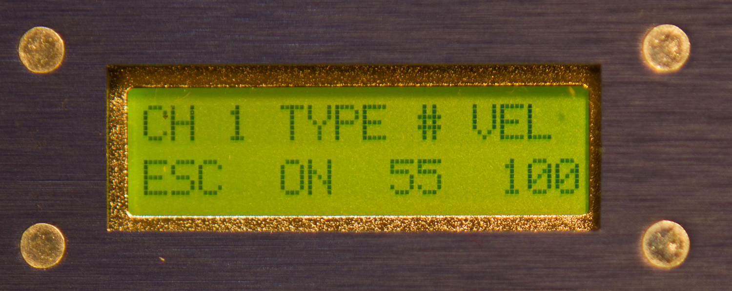
Next, a MIDI note off message was transmitted:
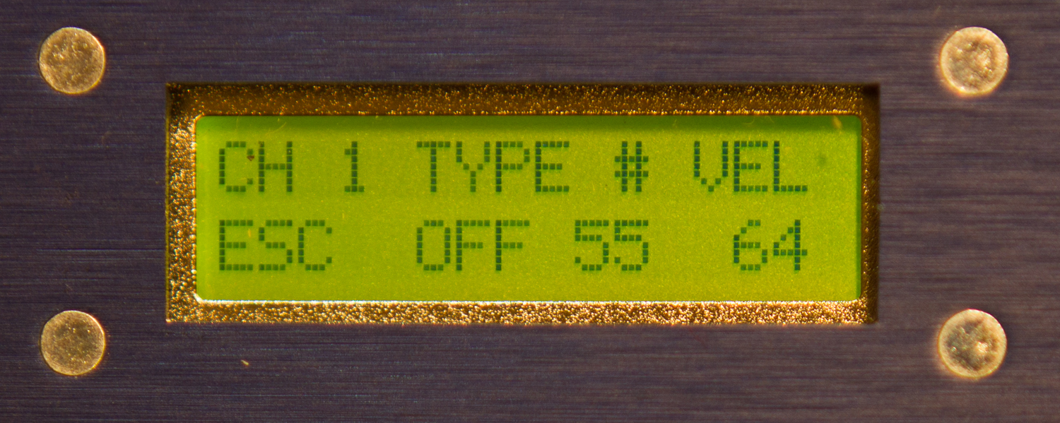
In MIDI monitor mode, NO DMX IS OUTPUT. Connected fixtures will not respond. This mode is useful for simply checking the status of transmitted data. To exit monitor mode and resume normal operation, press the left button, ‘ESC’.
Step 4: Exit ‘MIDI Monitor’ and Drive the Lighting Equipment
The DecaBox responds to Note, Program / Patch Change (PC) and Continuous Controller (CC) messages. Each will be discussed in turn.
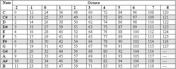
There are 128 notes in a MIDI scale. Each note is assigned a number. Middle C is #60. Depending on the equipment manufacturer, this note is also called C3, C4 or C5. What’s most important to know is that the very lowest possible MIDI note on the scale, C0 (or C-1, or C-2, depending on who is writing the documentation) has a number of ‘0’. The very highest possible note in a MIDI scale is G8 or G9, and it has a value of 127. Here are a pair of examples:
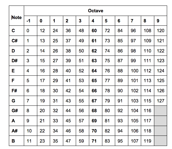
MIDI scale starting at C-1
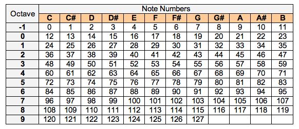
MIDI scale starting at C0
What’s important to understand is that no matter the naming convention, the DecaBox maps the first MIDI note in the scale (C-1, C0, etc) to DMX channel 1. The highest possible note in the scale corresponds to DMX channel 128.
Then, the DecaBox converts the MIDI note velocity to DMX data by doubling it. Note velocity corresponds to loudness, if the notes were played on a piano. When keys are barely touched, velocities are very low. If pounded as loudly as possible, the note velocity will be high. In the MIDI world, note velocities are a 7-bit value and cover the range [0 127].
DMX is an 8-bit system, which means levels can vary over 256 discrete steps. Their valid range is [0 255]. The DecaBox doubles the incoming MIDI note velocity to create DMX channel values.
Example: An RGB Stage Light
Every lighting equipment manufacturer sets up their equipment in a slightly different way. For this reason, it’s essential to consult the equipment manual during programming to determine the ‘DMX Channel Map’.
A very basic example would be an RGB stage light. It could be designed to run in several different modes:
- 3 channels. Three consecutive DMX channels drive red, green and blue. Super simple to operate.
- 4 channels. As above, but a fourth channel controls ‘master intensity.’ If this fourth channel is turned off, the fixture will appear unresponsive.
- 5+ channels. As above, but some fixtures include built-in effects such as sound activation, color cycling, strobing in various colors and at different speeds. The map for one of these systems might look like this:
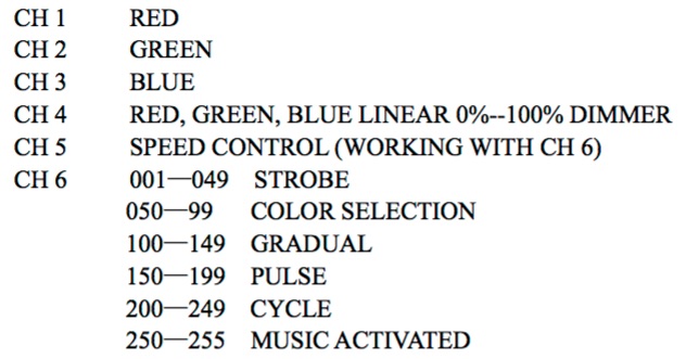
To make this particular fixture work properly, DMX channel 4 must always be set to 100%. Without channel 4 being turned on, the fixture will appear unresponsive. If written on a musical staff, this would correspond to a whole note which lasts for many measures:

Then, other notes are added and removed, corresponding to different colors. In some cases, these may appear to be very ugly chords indeed.
The Internal Dimming Engine
It can be useful to slowly fade lights up and down. One method to set this up in a sequencer is to transmit a series of 16th (or even 32nd) notes, with ever increasing or decreasing velocity / loudness levels, to the DecaBox:
However, this can be tedious and is in fact unnecessary. The DecaBox includes a 128 built-in dimming engines, one for each DMX channel. These engines run simultaneously and in parallel, and can be set to any speed at any time.
Here’s how it works:
On the main screen, the LCD indicates the currently selected fade speed. In this case, S = 0, signifying instantaneous changes. The speed is changed by sending a MIDI Patch Change / Program Change message. A patch change message is used to specify a MIDI instrument, such as grand piano, pipe organ, bass drum, etc.
There are 128 programs in the general MIDI command set, and each has a corresponding value in the range [0 127]. The DecaBox receives these messages and multiplies their value by 0.25 seconds. Thus a basic acoustic piano corresponds to instant changes, a pipe organ (#17) sets the engine to an approximate 4 second fade time, and so forth.
In this photo, the message ‘change to Kalimba’ was sent:
What’s useful is that MIDI note messages and PC messages may be interleaved in any combination. The most recently received PC message sets the dimming speed for all subsequent note messages until a new PC message is received.
For example, suppose channels 1, 2 and 3 should fade up slowly. But while they are fading, channel 4 should flash on and off instantly. Here’s the message flow:
-
PC#81 (synth, sets the fade speed to 80 * 0.25 seconds = 20 seconds)
-
Note On #1 Velocity 127 (100% brightness)
-
Note On #2 Velocity 127
-
Note On #3 Velocity 127
-
Wait 1-2 seconds
-
PC#0 (piano, sets the fade speed to 0 * 0.25 seconds = 0 seconds)
-
Note On #4
-
Wait 1 second
-
Note Off #4
-
Wait 1 second
-
Note On #4
-
Wait 1 second
-
Note Off #4
-
(At this point, DMX channels 1, 2 and 3 are still slowing fading up)
-
PC#4 (piano, sets fade speed to 4 x 0.25 seconds = 1 second)
-
Note Off #1, #2, #3
Drive the DMX Engine Using MIDI Continuous Controller (CC) Messages
The Decabox also responds to MIDI CC messages. These messages correspond to varying parameters in a composition. Some common names include ‘modulation’ or ‘knob controller’ or ‘general purpose wheel.’ In any case, there are 128 MIDI CC messages, each with a unique number. The Decabox accepts the first 119 general-purpose messages and maps them 1:1 to the first 119 DMX channels.
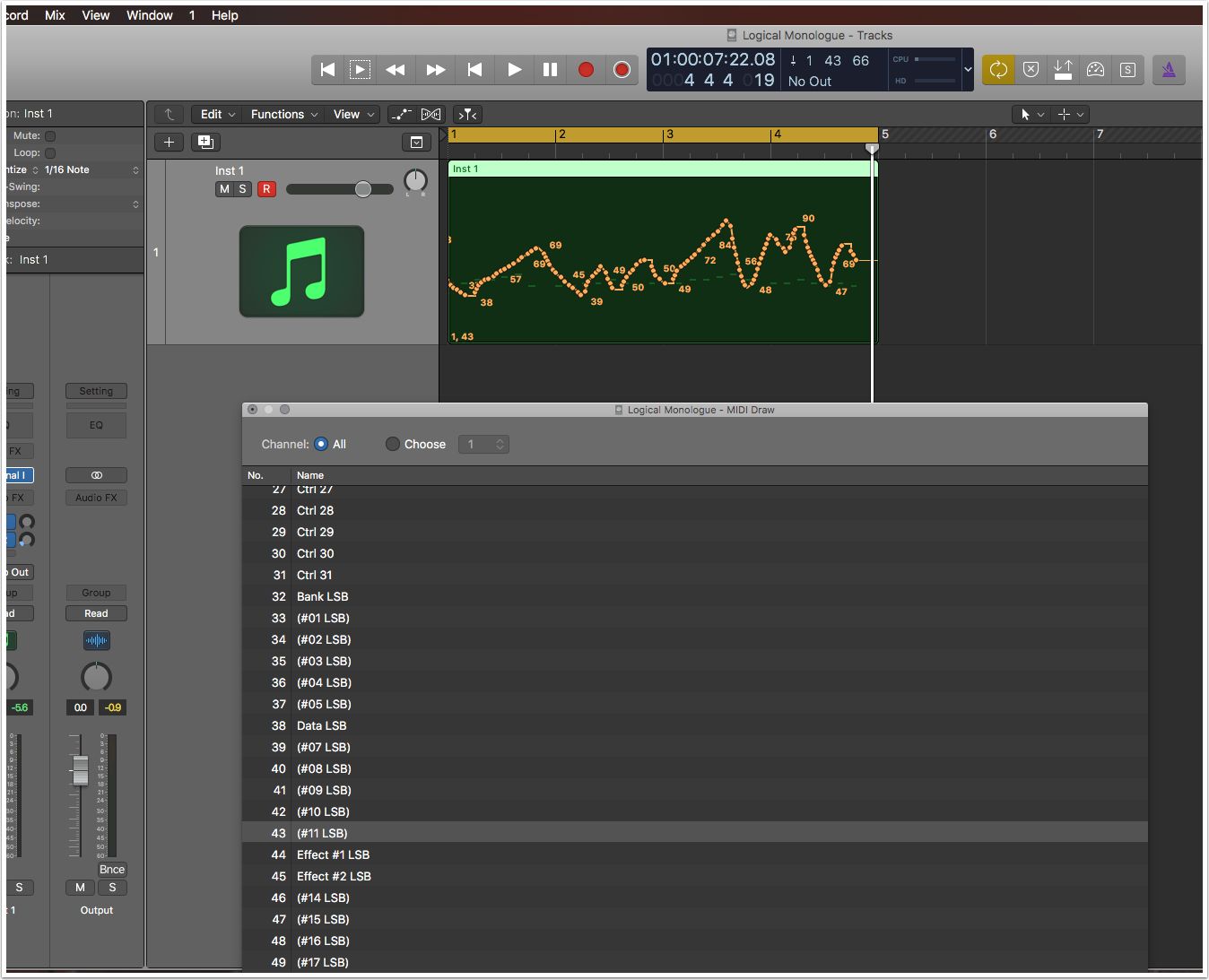
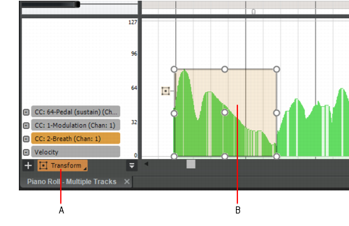
In a sequencer program, MIDI CCs can often be represented by a knob, slider or even drawn freehand with a pencil tool:
By using CC messages, complicated lighting transitions can easily be created within a MIDI sequencing suite.
References
If reading this document online, these links should be live and clickable:
- A good overview of the DMX512 standard, including timing information and protocol history: https://en.wikipedia.org/wiki/DMX512
- One of MIDI octave naming conventions: http://www.pgmusic.com/forums/ubbthreads.php?ubb=showflat&Number=338513
- MIDI patch / program change messages: https://www.midi.org/specifications/item/gm-level-1-sound-set
- MIDI CC messages and standard names: http://www.nortonmusic.com/midi_cc.html
DMX-512 for Musicians: a Quick Analogy
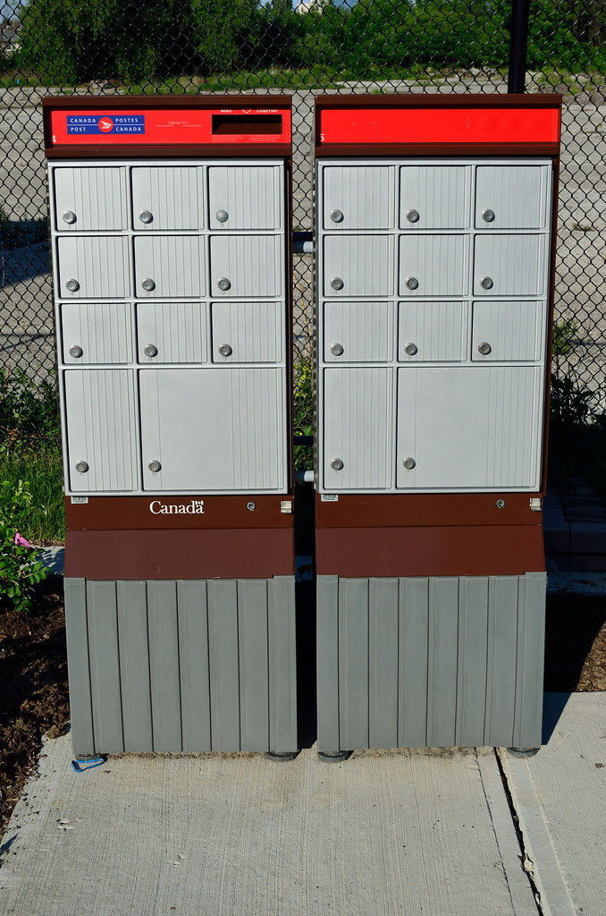
Picture a wall of mailboxes in an apartment building or post office. The mail is delivered each morning. If you have a key or combination for a particular box, you can remove your mail at any convenient time after it’s been delivered.
A DMX datastream is like a wall of 512 mailboxes which are refilled between 20 and 40 times each second. Every device connected to a DMX system is assigned a start address.
This address tells each piece of equipment which 'door' in the PO Box wall to look behind to find the correct data. An 8- channel dimmer pack could be assigned a start address of 15. The dimmer's internal processor then knows to look behind doors 15-22 (8 channels total) to find lighting information for each of its outputs.
This start address is usually set using small switches or pushbuttons, and each manufacturer describes how to set the address in their instruction manual.
An RGB wash light could be assigned a start address of 6. This means that doors (or DMX channels) 6, 7 and 8 control the fixture's red, green and blue lights. As the value of each DMX channel varies, the intensity of those primary colors goes up and down in sync.
In most installations, each piece of equipment is assigned a unique and non-overlapping start address. A small stage setup could be designed this way:
|
Fixture Description |
Channels Required |
DMX Start Address |
|
Dimmer Pack #1 |
4 |
60 |
|
Dimmer Pack #2 |
4 |
64 |
|
RGB Flood Light |
3 |
68 |
|
RGB Flood Light |
3 |
71 |
|
RGB Flood Light |
3 |
74 |
Note: The definition of ‘channel’ in the DMX world is totally different than ‘channel’ in the MIDI world. There are 512 DMX channels in a universe. This means that 512 separate light bulbs could be connected to 512 one-channel dimmer packs, and their brightness can be controlled by a single lighting desk. There are 16 MIDI channels. A single MIDI channel can be compared to a pipeline through which data can pass. 128 notes are available in each MIDI channel.
Purchasing
If you've landed here via a web search, don't already own one of these systems, but would like to add one to your collection, our online store is here:
www.response-box.com/gear/shop
And our main site is here, which includes links to distributors, etc:
Case Study - A Series of Generic LED PARs from Asia
We've all seen this sort of light for ~$30 via the usual sources. A customer wanted to control about a dozen of them, discretely. It made sense to document the setup in case the scenario is useful to others.
The first step is to figure out which DMX modes are available. Often these fixtures contain 3-channel (RGB) modes, 7+ channel (RGB + color fade + strobe, etc) modes and more. Typically in these situations, we pick the simplest mode first. Once this is stable, it's easy to work backwards.
(Yes, the instructions are in Spanish. But the gist is pretty clear.)
This fixture supports 4-channel (RGBW) and 8-channel modes:
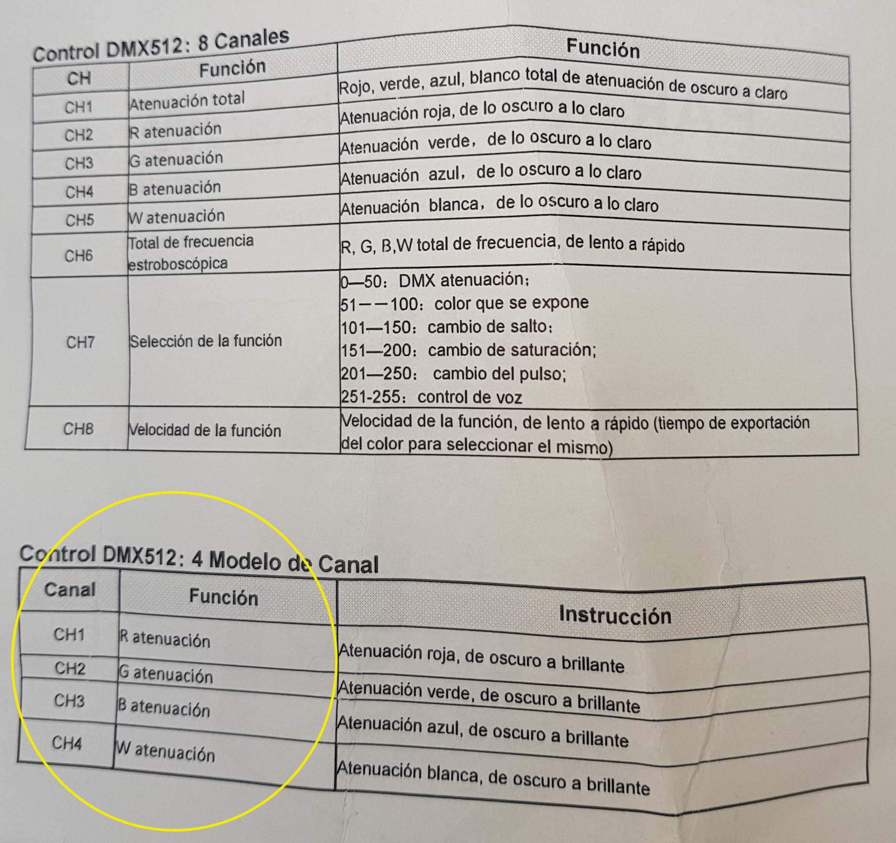
So to get started, we'll choose 4 channel mode, since that's straight, simple control of RGB and white, without any 'master brightness' channels to worry about.
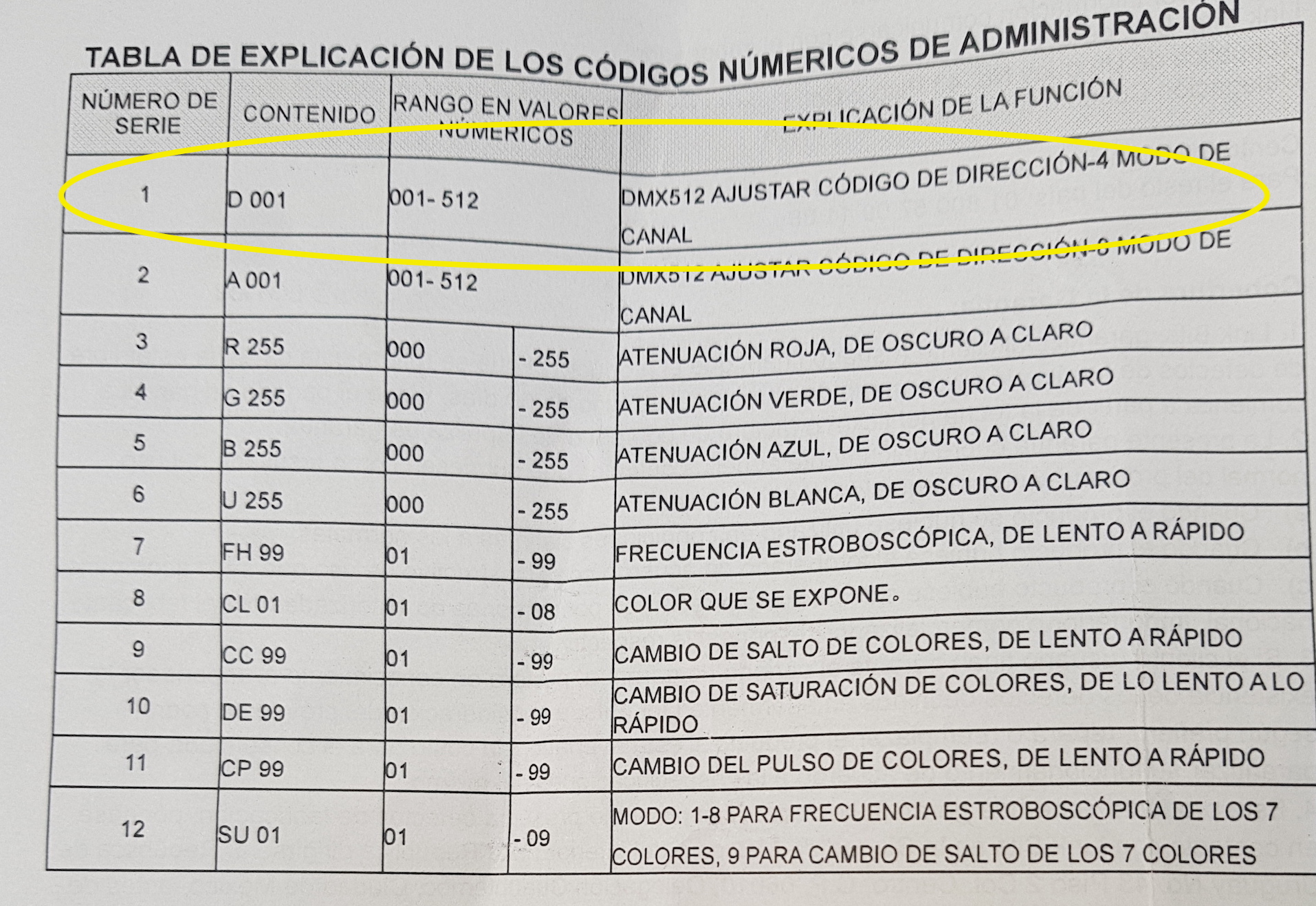
Next, the fixture must be set to 4 channel mode. Using the fixture's pushbuttons, we choose 'dXXX' where XXX is the start address. For easy of connecting to a MIDI system, set this address to 60 (middle C) for now:
Then, since the MIDI to DMX bridge maps MIDI notes (which are each numbered, range is [0 127] with middle C being 60, we know that there should be control of this fixture by playing notes like this:
Middle C Note #60 'Red' DMX Start address = 60
Middle C# Note #61 'Green' DMX start address + 1
Middle D Note #62 'Blue' DMX start address + 2
Middle D# Note #63 'White' DMX start address + 3Now, to control multiple fixtures discretely, they need to have start addresses which are offset by 4 channels. So setting the fixtures like this should work:
Fixture 1 Address 60
Control with Middle C, C#, D, D#
Fixture 2 Address 64
Control with E, F, F#, G
Fixture 3 Address 68
Control with G#, A, Bb, B
etc...
Note: there's no reason why the first fixture couldn't have its address set to 001, which can be accessed by the very lowest C note on the MIDI scale. However, on some keyboards / systems its a hassle to transpose octaves like this, so it makes things simple to start somewhere obvious, near the middle of the scale, and then work backwards for final production settings.